| Creating a PIC32MZ HighSpeed USB HOST program | 2025.10.12 |
[Japanes][English]
1. overview
I have created a USB HOST program using the PIC32MZ HighSpeedUSB module, and would like to release it to the public.
It does not use the Harmony library provided by Microchip.
The created HOST driver has a built-in HUB driver and is multi-interface and multi-device compatible.
It is possible to operate a USB device with multiple interfaces (for example, a mouse interface and a keyboard interface) or multiple USB devices connected using an external HUB.
Up to four devices can be operated simultaneously: USB mouse, USB keyboard, USB game controller, USB MIDI keyboard, USB serial converter, and USB memory.
USB camera is not supported in the current version (under development).
2. Project file
Download the project file below, compile it, and then use a programmer such as PICKit3 to write it to the PIC32MZ on the evaluation board (described later).
-
Project file: PIC32MZ_USB_HOST_with_HUB.zip
Source file list
The compilation environment is as follows:
-
Microchip MPLAB X IDE Ver6.20, XC32 compiler ver 4.60
X IDE encoding is SHIFT JIS. ( Screen Shot)
Set the heap size of XC32 Linker option to 10240. (Screen Shot)
(Note) PICKit3 can be used up to X IDE ver6.2. It cannot be used with ver6.25.
3. Evaluation board
To evaluate and check the operation of the created HOST program, we created an evaluation board using a PIC32MZ2048EFH100 microcontroller.
The circuit diagram is as follows: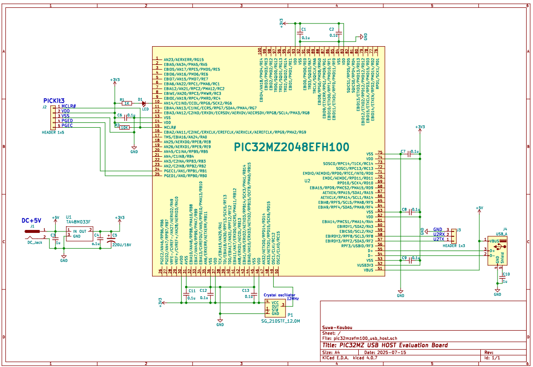
|
This is the evaluation board I made. It also has parts that are not necessary for evaluating the HOST program.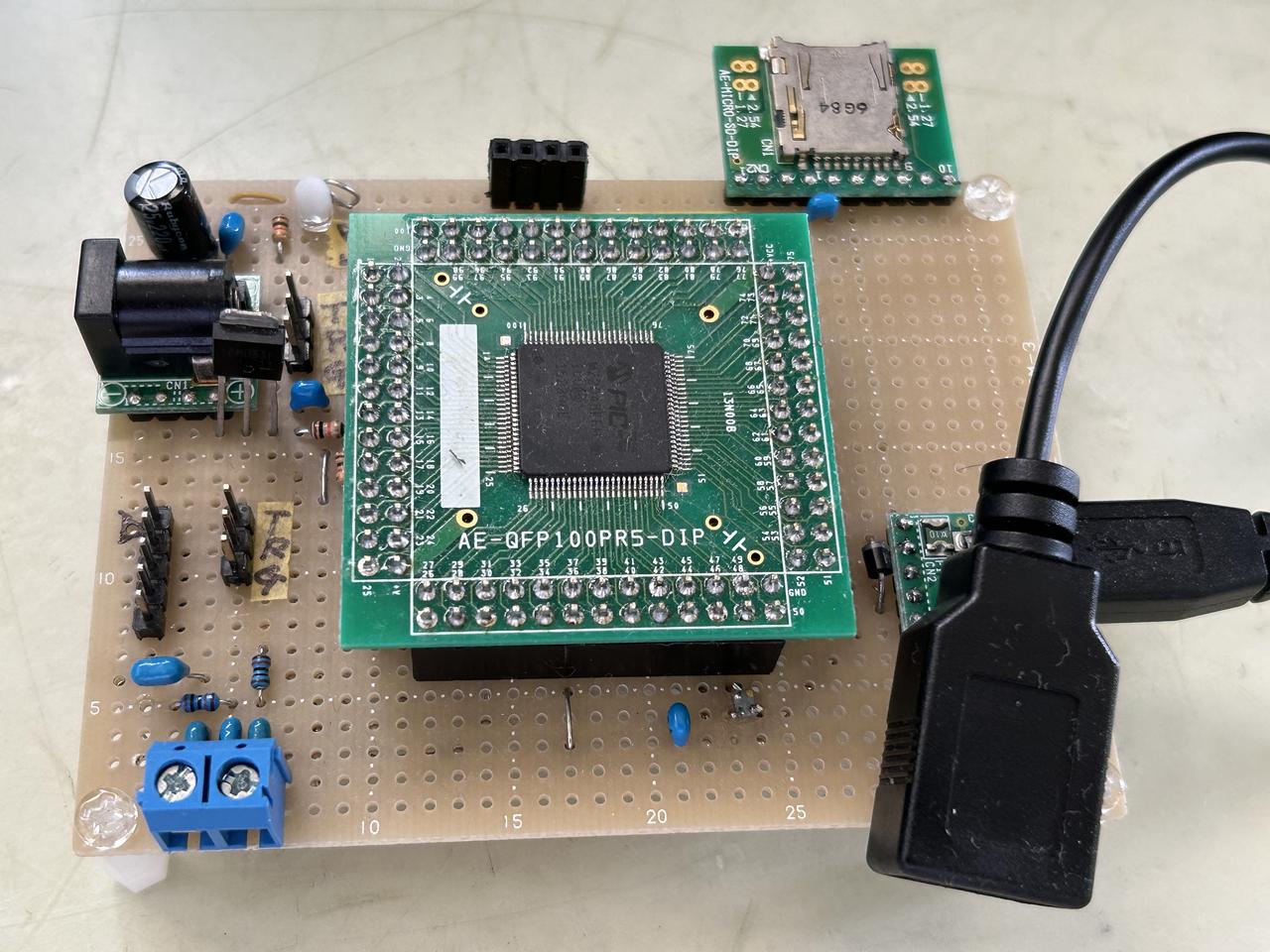 |
The PIC32MZ2048EFH100 microcontroller used was an early version, so it was not possible to use a crystal resonator for clock oscillation, and so the clock was supplied from a crystal oscillator.
To use the USB module, the clock frequency must be 12MHz or 24MHz. In this build, a 12MHz crystal oscillator was used due to availability.
If you want to use a 24MHz crystal oscillator, change the file pic32mz_config.h
-
Configure 12MHz
// DEVCFG2
#pragma config FPLLIDIV = DIV_3 // System PLL Input Divider (3x Divider)
#pragma config FPLLRNG = RANGE_5_10_MHZ // System PLL Input Range (Bypass)
#pragma config FPLLICLK = PLL_POSC // System PLL Input Clock Selection (POSC is input to the System PLL)
#pragma config FPLLMULT = MUL_100 // System PLL Multiplier (PLL Multiply by 100)
#pragma config FPLLODIV = DIV_2 // System PLL Output Clock Divider (2x Divider)
#pragma config UPLLFSEL = FREQ_12MHZ // USB PLL Input Frequency Selection (USB PLL input is 12 MHz)
Configure 24MHz
// DEVCFG2
#pragma config FPLLIDIV = DIV_3 // System PLL Input Divider (3x Divider)
#pragma config FPLLRNG = RANGE_5_10_MHZ // System PLL Input Range (Bypass)
#pragma config FPLLICLK = PLL_POSC // System PLL Input Clock Selection (POSC is input to the System PLL)
#pragma config FPLLMULT = MUL_50 // System PLL Multiplier (PLL Multiply by 100)
#pragma config FPLLODIV = DIV_2 // System PLL Output Clock Divider (2x Divider)
#pragma config UPLLFSEL = FREQ_24MHZ // USB PLL Input Frequency Selection (USB PLL input is 12 MHz)
UART1 or UART3 can also be used instead of UART2, but if you use something other than UART2, please change the following.
The printf() function is used to output messages. The following function is written at the beginning of uart2.c to connect the printf() output to UART2.
    // Override _mon_putc to allow printf to send characters over UART2
    void _mon_putc (char c)
    {
        if(c=='\n') UART2PutChar('\r');
        UART2PutChar(c);
    }
If you are using UART1 or UART3, place the same function somewhere.
In addition, you need to change the input/output settings used to test the USB memory's FatFile system .
    ff_test.c 208Line to 209Line
    xdev_in(UART2GetChar);
    xdev_out(UART2PutChar);
Please modify it to suit UART1 or UART3.To set up the UART, you need to remap the port. Please also modify the relevant part of InitializeSystem() at the end of main.c. Also , please change the macros such as putstr() and getch() written in debug.h to match the UART you are using .
In the test demo program in main.c , an LED is displayed to let you know if the connected USB device is recognized by the HOST. The LED is connected to RG6. If you want to use another port, please modify the corresponding part of InitializeSystem() at the end of main.c and the define statement at the beginning .
I used a +5V output AC adapter to power the board. A regulator power voltage down to 3.3V and supplies it to the microcontroller. The +5V output of the AC adapter also powers the USB device from VBUS, so please use one with an output of at least 1A.
4. Evaluation and operation check
Once you have created the board, compiled the project file, and written it to the microcontroller, you can check that it works.
First, connect the UART2 output terminal to a PC using a USB-serial converter. Use a terminal program such as TeraTerm on the PC. The serial port parameters are 115200bps, 8-bit data length, 1-bit stop, no parity, and no flow control .
Next, connect the AC adapter to the power connector on the board to supply power.
If the following message appears on the TeraTerm screen (hereafter referred to as the console screen) on your PC, the program has started up normally. This display will be referred to as the "Main Menu" from here on.
-
**** PIC32MZ High Speed USB Host Module Evaluation *****
select evaluation USB Device
1: mouse
2: keyboard
3: midi
4: serial
5: game controller(HID generic)
6: usb memory
==>
By entering numbers 1 to 6, you can test each USB device. During the test, you can return to the main menu by pressing ctrl+'C' (although this may not be the case).
When you connect the USB device you want to test to the USB connector while the main menu is displayed, the HOST program will recognize the device and the LED on the board will light up. When you remove the device, the LED will go out.
The LED will not light up just by connecting the HUB to the USB connector. The LED will light up when you connect a device to the port of the connected HUB. However, if you connect a device that is not on the main menu, the LED will not light up.
If you connect devices to multiple ports on the HUB and then remove the devices, the LEDs will remain lit until all devices are removed.
You can connect and use any hub, from USB 1.1 to USB 3.0. We have not confirmed anything beyond USB 3.0. For USB 1.1 hubs, use FullSpeed, and for anything above that, use HighSpeed.
When connecting multiple devices that consume a lot of power, such as USB memory sticks, use a self-powered hub rather than a bus-powered hub. Even if you can connect them, if the VBUS voltage fluctuates when accessing the devices after that, the microcontroller may not operate properly.
A HUB connected to a HUB port (cascade HUB) cannot be used.
If you connect multiple devices through the HUB and enter the numbers to test the devices, the following device selection menu will appear.
-
2 device connects
which device (0 - 1) =>
If you have only one device connected, this menu will not appear and device 0 will be tested.
If you enter any of the numbers 1 to 6 before connecting a USB device, for example, if you enter number 2 and select the keyboard test,
    Wait for USB Keyboard connect.
    Hit ctrl+C to test cancel.
If you connect a keyboard,
-
1 Keyboard connects
4-2. Mouse testing
Enter number 1 to perform a mouse test. In the mouse test, you can check the mouse data and the change of mouse protocol.
When you move the mouse, the mouse data will be displayed on the screen as shown below.
-
mouse dev0: 00 FE 00 00
mouse dev0: 00 FF 00 00
mouse dev0: 00 FC 00 00
mouse dev0: 00 FE FF 00
mouse dev0: 00 FE FD 00
mouse dev0: 00 00 FD 00
mouse dev0: 00 00 FA 00
Newer mice that connect with a wireless receiver send data in 16 bits. Modern multi-function mice may send even more data.
-
mouse dev1: 01 00 F7 FF F2 FF 00 00
mouse dev1: 01 00 F7 FF F4 FF 00 00
mouse dev1: 01 00 F6 FF F2 FF 00 00
mouse dev1: 01 00 F7 FF F4 FF 00 00
mouse dev1: 01 00 F8 FF F5 FF 00 00
mouse dev1: 01 00 F9 FF F8 FF 00 00
In the case of the mouse in the example, the Report protocol will handle 16-bit data, and the Boot protocol will handle 8-bit data.
-
mouse dev1: 01 00 00 00 FC FF 00 00
mouse dev1: 01 00 FF FF FC FF 00 00
mouse dev1: 01 00 00 00 FD FF 00 00
mouse dev1: 01 00 00 00 FF FF 00 00
mouse dev1: 00 02 02 00
mouse dev1: 00 00 01 00
mouse dev1: 00 00 01 00
mouse dev1: 00 00 01 00
mouse dev1: 01 00 02 00 01 00 00 00
mouse dev1: 01 00 01 00 01 00 00 00
mouse dev1: 01 00 00 00 01 00 00 00
mouse dev1: 01 00 01 00 00 00 00 00
mouse dev1: 00 00 01 00
mouse dev1: 00 FE FF 00
mouse dev1: 00 FF FD 00
mouse dev1: 00 00 FF 00
mouse dev1: 01 00 01 00 01 00 00 00
mouse dev1: 01 00 01 00 03 00 00 00
mouse dev1: 01 00 01 00 00 00 00 00
For the API of the HOST program used in the mouse test, including other devices, please refer to PIC32MZ HighSpeed USB HOST Application Interface .
4-3. Keyboard test
Entering number 2 will perform a keyboard test. The keyboard test allows you to check the reading of key data and the control of turning the keyboard LEDs on and off.
When the test starts, data from the keyboard is displayed. When there is no key operation, the data is 00 00 00 00 00 00 00 , but the data will change if any key is pressed.
-
keyboard dev0: 00 00 00 00 00 00 00 00
keyboard dev0: 00 00 00 00 00 00 00 00
keyboard dev0: 00 00 00 00 00 00 00 00
keyboard dev0: 00 00 00 00 00 00 00 00
keyboard dev0: 01 00 00 00 00 00 00 00
keyboard dev0: 01 00 8B 00 00 00 00 00
keyboard dev0: 01 00 8B 11 00 00 00 00
keyboard dev0: 09 00 8B 11 00 00 00 00
keyboard dev0: 09 00 8B 00 00 00 00 00
keyboard dev0: 09 00 00 00 00 00 00 00
keyboard dev0: 09 00 59 00 00 00 00 00
keyboard dev0: 09 00 59 8B 00 00 00 00
keyboard dev0: 09 00 59 8B 2C 00 00 00
keyboard dev0: 09 00 59 8B 2C 11 00 00
keyboard dev0: 01 00 59 8B 2C 11 00 00
If the scan code needs to be converted to a key character, the conversion process is the application's responsibility.
Next, press the number 1 on the keyboard , and each time you press it, the three LEDs on the keyboard, CapsLock, NumLock, and ScrlLock, will light up and go off in sequence.
4-4. MIDI input test
Entering number 3 will perform an input test from the MIDI device. If you connect a USB-MIDI keyboard, the data from the MIDI keyboard will be read and displayed on the screen.
-
midi dev0: 09 90 30 63
midi dev0: 08 80 30 40
midi dev0: 09 90 32 6E
midi dev0: 08 80 32 40
midi dev0: 09 90 34 6E
midi dev0: 08 80 34 40
midi dev0: 09 90 35 76
midi dev0: 08 80 35 40
midi dev0: 09 90 37 76
midi dev0: 08 80 37 40
In this demo test, we only read data from the connected MIDI device, but it is also possible to send data to a MIDI device.
When creating an application, please refer to the PIC32MZ HighSpeed USB HOST Application Interface .
4-5. Serial transmission and reception test
Entering number 4 will perform a test of sending and receiving data on the USB serial device.
Character data typed on the console screen will be sent to the other side via the serial device.
Data sent from the other side will be received and displayed on the console screen.
The serial communication parameters are set to the defaults of 115200bps, 8-bit data length, 1-bit stop, no parity, and no flow control
when a serial device is recognized.
Parameters can be changed through the API. See PIC32MZ HighSpeed USB HOST Application Interface
4-6. Game controller (HID generic) test
Entering number 5 will perform an input test for the USB game controller.
When you connect a game controller, it will read the data of the joystick and buttons on the controller and display it on the screen.
-
Game Controller dev0: FF 80 9C 00 01 08 00 08
Game Controller dev0: FF 80 A2 00 01 08 00 08
Game Controller dev0: FF 80 B8 00 01 08 00 08
Game Controller dev0: FF 80 D2 00 01 08 00 08
Game Controller dev0: FF 80 DF 00 01 08 00 08
Game Controller dev0: FF 80 E4 00 01 08 00 08
Game Controller dev0: FF 80 DF 00 01 08 00 08
Game Controller dev0: FF 80 CF 00 01 08 00 08
Game Controller dev0: FF 80 B4 00 01 08 00 08
In reality, the data can be interpreted by reading the report descriptor, but this determination process is complicated.
Therefore, in practice, we move the controller and check and identify which part of the data changed when a certain button was pressed. The same idea applies to mice and keyboards.
The host program does not support reading the report descriptor.
You can also connect and test HID generic devices (such as PICKit3) other than game controllers, but if the device does not send data spontaneously, no data will be displayed on the screen.
Generally, some protocol is used, and it will not work unless you send data according to that protocol.
It is possible to send data to HID generic devices. See PIC32MZ HighSpeed USB HOST Application Interface .
4-7. Testing the USB memory
Enter number 6 to test the USB memory.
When the host program detects the connection of a USB memory, it performs enumeration and then issues the SCSI command TEST_UNIT_READY to check whether the memory is ready.
The check takes 2.5 seconds. The result of the check is stored inside the HOST program, and if the ready state cannot be confirmed, an error occurs when reading from or writing to this device.
If the device is unready, try disconnecting it and reconnecting it.
When you start the test, the following processing menu will be displayed.
-
1:Read Capacity
2:Sector Read
3:Sector Write
4:Fat File System
==>
-
Last Sector Number = 0x0001F3FF(127999)
If you enter 2 , the memory contents will be read and displayed in sector units.
Enter the starting sector number and the number of sectors to read.
-
Last Sector Number = 127999
Read Start Sector =>0
number of sectors =>3
-
*** Sector 0 Start Addr=0000000000
-- addr -- +0 +1 +2 +3 +4 +5 +6 +7 +8 +9 +A +B +C +D +E +F ---- ASCII -----
0000000000 EB 3C 90 4D 53 44 4F 53 35 2E 30 00 02 02 06 00 .<.MSDOS5.0.....
0000000010 02 00 02 00 00 F8 F9 00 3F 00 FF 00 00 00 00 00 ........?.......
0000000020 00 F4 01 00 80 01 29 0F 71 81 C8 4E 4F 20 4E 41 ......).q..NO NA
0000000030 4D 45 20 20 20 20 46 41 54 31 36 20 20 20 33 C9 ME FAT16 3.
0000000040 8E D1 BC F0 7B 8E D9 B8 00 20 8E C0 FC BD 00 7C ....{.... .....|
0000000050 38 4E 24 7D 24 8B C1 99 E8 3C 01 72 1C 83 EB 3A 8N$}$....<.r...:
0000000060 66 A1 1C 7C 26 66 3B 07 26 8A 57 FC 75 06 80 CA f..|&f;.&.W.u...
0000000070 02 88 56 02 80 C3 10 73 EB 33 C9 8A 46 10 98 F7 ..V....s.3..F...
0000000080 66 16 03 46 1C 13 56 1E 03 46 0E 13 D1 8B 76 11 f..F..V..F....v.
0000000090 60 89 46 FC 89 56 FE B8 20 00 F7 E6 8B 5E 0B 03 `.F..V.. ....^..
00000000A0 C3 48 F7 F3 01 46 FC 11 4E FE 61 BF 00 00 E8 E6 .H...F..N.a.....
00000000B0 00 72 39 26 38 2D 74 17 60 B1 0B BE A1 7D F3 A6 .r9&8-t.`....}..
00000000C0 61 74 32 4E 74 09 83 C7 20 3B FB 72 E6 EB DC A0 at2Nt... ;.r....
00000000D0 FB 7D B4 7D 8B F0 AC 98 40 74 0C 48 74 13 B4 0E .}.}....@t.Ht...
00000000E0 BB 07 00 CD 10 EB EF A0 FD 7D EB E6 A0 FC 7D EB .........}....}.
00000000F0 E1 CD 16 CD 19 26 8B 55 1A 52 B0 01 BB 00 00 E8 .....&.U.R......
0000000100 3B 00 72 E8 5B 8A 56 24 BE 0B 7C 8B FC C7 46 F0 ;.r.[.V$..|...F.
0000000110 3D 7D C7 46 F4 29 7D 8C D9 89 4E F2 89 4E F6 C6 =}.F.)}...N..N..
0000000120 06 96 7D CB EA 03 00 00 20 0F B6 C8 66 8B 46 F8 ..}..... ...f.F.
0000000130 66 03 46 1C 66 8B D0 66 C1 EA 10 EB 5E 0F B6 C8 f.F.f..f....^...
0000000140 4A 4A 8A 46 0D 32 E4 F7 E2 03 46 FC 13 56 FE EB JJ.F.2....F..V..
0000000150 4A 52 50 06 53 6A 01 6A 10 91 8B 46 18 96 92 33 JRP.Sj.j...F...3
0000000160 D2 F7 F6 91 F7 F6 42 87 CA F7 76 1A 8A F2 8A E8 ......B...v.....
0000000170 C0 CC 02 0A CC B8 01 02 80 7E 02 0E 75 04 B4 42 ............u..B
0000000180 8B F4 8A 56 24 CD 13 61 61 72 0B 40 75 01 42 03 ...V$..aar.@u.B.
0000000190 5E 0B 49 75 06 F8 C3 41 BB 00 00 60 66 6A 00 EB ^.Iu...A...`fj..
00000001A0 B0 42 4F 4F 54 4D 47 52 20 20 20 20 0D 0A 52 65 .BOOTMGR ..Re
00000001B0 6D 6F 76 65 20 64 69 73 6B 73 20 6F 72 20 6F 74 move disks or ot
00000001C0 68 65 72 20 6D 65 64 69 61 2E FF 0D 0A 44 69 73 her media....Dis
00000001D0 6B 20 65 72 72 6F 72 FF 0D 0A 50 72 65 73 73 20 k error...Press
00000001E0 61 6E 79 20 6B 65 79 20 74 6F 20 72 65 73 74 61 any key to resta
00000001F0 72 74 0D 0A 00 00 00 00 00 00 00 AC CB D8 55 AA rt............U.
*** Sector 1 Start Addr=0000000200
-- addr -- +0 +1 +2 +3 +4 +5 +6 +7 +8 +9 +A +B +C +D +E +F ---- ASCII -----
0000000200 00 00 00 00 00 00 00 00 00 00 00 00 00 00 00 00 ................
0000000210 00 00 00 00 00 00 00 00 00 00 00 00 00 00 00 00 ................
0000000220 00 00 00 00 00 00 00 00 00 00 00 00 00 00 00 00 ................
...
...
Enter 3 to write data to the specified sector.
Enter the sector number to write to, then enter the data to write, one byte at a time.
-
Last Sector Number = 127999
Write Sector =>2
Write Data
=>0x30
=>0x31
=>0x32
=>0x33
=>0x34
=>0x35
=>0x
512 bytes of data will be written. Any part of the input data less than 512 bytes will be filled with 0x00 .
Enter 4 to test the FatFile system.
The following message will appear, and you will be prompted to enter a test command.
-
FatFs module test monitor for PIC32MZ
LFN=Enabled, CP= 932
Current time is 2025/7/16 0:08:25.
>
Enter ? to display the following command help:
-
[Disk contorls]
di <pd#> - Initialize disk
dd [<pd#> <lba>] - Dump a secrtor
ds <pd#> - Show disk status
[Buffer controls]
bd <ofs> - Dump working buffer
be <ofs> [<data>] ... - Edit working buffer
br <pd#> <lba> [<count>] - Read disk into working buffer
bw <pd#> <lba> [<count>] - Write working buffer into disk
bf <val> - Fill working buffer
[File system controls]
fi <ld#> - Force initialized the volume [ex. fi 0: fi 1: fi 2: fi 3: ]
fs [<path>] - Show volume status
fl [<path>] - Show a directory
fL <path> <pattern> - Directory search
fo <mode> <file> - Open a file. [mode: 1=read, 2=write 4=create]
fc - Close the file
fe <ofs> - Move fp in normal seek
fd <len> - Read and dump the file
fr <len> - Read the file
fw <len> <val> - Write to the file
fn <org.name> <new.name> - Rename an object
fu <name> - Unlink an object
fv - Truncate the file at current fp
fk <name> - Create a directory
fa <atrr> <mask> <object name> - Change attribute of an object
ft <year> <month> <day> <hour> <min> <sec> <name> - Change timestamp of an object
fx <src.file> <dst.file> - Copy a file
fg <path> - Change current directory
fq - Show current directory
fb <name> - Set volume label
fm <ld#> <type> <csize> - Create file system
fz [<len>] - Change/Show R/W length for fr/fw/fx command
[Misc commands]
t [<year> <mon> <mday> <hour> <min> <sec>] - Set/Show RTC
? --Show this Help message
r --exit, return to USB Memory test menu
For details, see FatFs - FatFs - Generic FAT Filesystem Module.
5. Related Documents
・PIC32MZ HighSpeed USB HOST Application Interface
・PIC32MZ HighSpeed USB HOST Software Document